
If you're halfway through an office fit-out, staring at a box of plugs, patch leads, containment drawings, CCTV schedules, access control requirements and an electrical sign-off date that isn’t moving, this is the point where small mistakes become expensive ones. Cat 5 plugs look trivial. They aren’t.
In UK commercial work, the plug at the end of the cable often decides whether a link sails through testing or sends your team back to re-terminate under pressure. That matters even more when the project isn’t just desks and phones. It might also involve CCTV, commercial electrical installation and certification, or building out fully autonomous unmanned building units where access, power and data all have to work together from day one.
An unmanned building in practice isn’t a futuristic idea. It usually means a site, suite, outbuilding or managed unit that runs without permanent on-site staff. Entry is controlled remotely or by credential, network services support sensors and cameras, and facilities teams expect lighting, security, comms and alarms to operate with minimal hands-on intervention. In those environments, bad terminations don’t just slow a laptop connection. They can knock out cameras, telephony, access points or linked systems that facilities managers depend on.
Why Cat 5 Plugs Can Make or Break Your Office Fit-Out
Most fit-out delays blamed on “the network” don’t start with switching or firewalls. They start much lower down, at the physical layer, where poor terminations create intermittent faults that nobody sees until testing day.
In the UK, structured cabling for commercial fit-outs is governed by BS 6701 and BS EN 50173, and that’s where the conversation needs to begin. It isn’t enough for a plug to look tidy. It has to support compliant performance across the installed link, especially if the project needs certification and warranty backing. That’s one reason a lot of teams reviewing network cables and cabling for modern offices end up realising the plug choice and termination method deserve more attention than they first gave them.
What goes wrong on live projects
The common failure pattern is simple. A legacy run gets reused, someone fits a new RJ45 plug, continuity looks fine, and the assumption is that the circuit is “done”. Then the certifier says otherwise, or the link behaves badly when it’s asked to carry modern traffic, PoE devices or integrated building systems.
That risk isn’t theoretical. Up to 40% of legacy Cat 5 installations fail modern gigabit speed tests due to plug-related crosstalk issues, according to the verified source provided for UK cable supplier data at Electronics Secret. Once that happens, performance suffers and warranty expectations can unravel quickly.
Practical rule: If a fit-out includes reused cabling, never assume the weak point is the horizontal run. The plug is often where the trouble starts.
Why this matters beyond desktop data
Office networks now carry far more than user traffic. The same environment may support:
CCTV feeds that need stable connectivity and predictable PoE delivery
Access control where door hardware, readers and controller links must remain dependable
Telephony and collaboration where poor terminations show up as voice instability before anyone blames cabling
Building systems in lightly staffed or unmanned spaces, where remote visibility matters more because nobody is there to intervene quickly
Many unmanned building projects fail for ordinary reasons, not exotic ones. The team treats security, electrical, access control and network cabling as separate packages. The lock installer assumes power is available. The electrical contractor assumes the IT team will handle data paths. The IT team inherits a cabinet full of badly labelled tails and mixed standards. Then the site goes live with avoidable single points of failure.
The fix starts with disciplined infrastructure. A correctly selected and properly terminated Cat 5 plug won’t make a bad design good, but a poor plug can absolutely make a good design fail.
Selecting the Right RJ45 Plug for Performance and Compliance
There isn’t one universal answer to cat 5 plugs. The right choice depends on cable type, environment, interference risk and how the link will be used once the building is occupied.

A lot of procurement mistakes happen because buyers treat every 8P8C plug as interchangeable. In practice, they’re not. The conductor type, plug body, load bar design and shielding all affect how easy it is to terminate cleanly and how likely the finished lead is to pass testing.
UTP or STP depends on the room
For standard office floors, UTP plugs are usually the sensible option. They’re straightforward, cost-effective and perfectly suitable where cable routes are well managed and segregation from mains and noisy services has been thought through.
STP plugs are worth considering when the environment is electrically busy. Typical examples include:
Server rooms and comms cupboards with dense equipment and bundled services
Areas close to mains distribution or electrical plant
CCTV infrastructure zones where power and data pathways can end up running in close proximity
Mixed-service risers where noise control becomes a practical concern
The trade-off is simple. STP can help in the right environment, but it also demands that the rest of the channel and installation approach support shielding properly. Using a shielded plug on an otherwise poorly planned route won’t rescue a bad design.
Standard plugs or pass-through plugs
Pass-through plugs divide opinion. They can speed up verification because the conductors pass through the nose of the plug, making wire order easier to check before crimping. For less experienced hands, that can reduce obvious pin-order mistakes.
Standard-load plugs still have advantages. They force cleaner prep, they avoid exposed trimmed ends at the nose, and many engineers prefer them where consistency matters more than speed.
A practical comparison looks like this:
Plug style | Where it works well | Main advantage | Main caution |
|---|---|---|---|
Standard RJ45 plug | Repeatable commercial work | Clean finished termination | Needs accurate trimming before insertion |
Pass-through RJ45 plug | Quick field assembly and visual checking | Easy to confirm wire order | Requires the correct pass-through crimper and tidy execution |
Shielded RJ45 plug | EMI-prone areas | Better fit for noisy environments | Only makes sense in a compatible screened approach |
For many office fit-outs, the key question isn’t which style is fashionable. It’s which style your team can terminate consistently, inspect properly and support during testing.
Cat 5, Cat 5e and mixing components
Legacy language causes confusion here. People still say “Cat 5 plugs” when they often mean plugs being used on Cat 5e-era infrastructure. That matters because the tolerance for sloppy work is lower once you expect modern performance from an older category baseline.
The safer approach is to match components carefully and avoid creating the lowest-performing point in the link. If you’re reviewing connector options alongside newer infrastructure, this guide to Cat 6 connectors and diagrams is useful for understanding where compatibility ends and compromise begins.
A good plug choice is the one that matches the cable, suits the environment and can be terminated the same way every time by the people actually doing the work.
Design choices for unmanned spaces
In unmanned building units, the plug decision sits inside a larger systems decision. Access, power and data have to be designed together. If a door relies on network-connected controls, if CCTV relies on PoE, and if remote support depends on stable switching, the termination quality at the edge becomes operational, not cosmetic.
That’s also why many projects choose battery-less, NFC proximity locks in smaller unattended spaces. The primary attraction isn’t novelty. It’s maintenance reduction. Batteries don’t need replacing on a service schedule, there’s less risk of lock failure caused by neglected cells, and facilities teams avoid another routine task across dispersed sites. Those locks still need the surrounding infrastructure planned properly, especially where readers, controllers, CCTV and communications all share the same building network.
The Professional's Toolkit for Flawless Terminations
Cheap tools create expensive faults. That’s as true for cat 5 plugs as it is for electrical work.
The best field engineers aren’t guessing with multipurpose bargain crimpers that flatten one plug nicely and half-crimp the next. They use tools that produce the same result repeatedly, because repeated work is what fit-outs demand.

The tools that actually matter
A proper kit for terminating RJ45 plugs should include the following as a minimum:
Ratcheting crimp tool. This gives consistent compression and reduces under-crimped plugs that pass a visual check but fail in use.
Precision jacket stripper. The outer sheath needs to come off cleanly without nicking the twisted pairs underneath.
Flush cutters. Clean, even conductor ends make insertion easier and reduce the chance of one core stopping short.
Basic tester and certifier access. A wiremap tester is helpful on the bench. It isn’t the end of the job.
Test fixture for pre-checking plugs. This is especially useful when you’re producing multiple patch leads under time pressure.
The point isn’t to own more tools. It’s to remove variation from the process.
Why the stripper matters more than people think
Most avoidable damage happens before the plug is even on the cable. If the jacket stripper bites too deep, you can mark or weaken the conductors while the cable still looks usable. That fault may not show itself until the lead is flexed, moved or put under load.
A precision stripper lets you score the sheath and peel it away without rough handling. It’s a small detail, but it protects signal integrity and saves time later.
Field note: If the prep work looks rushed, the certifier usually proves it later.
A lot of newer engineers improve quickly once they see a good termination done at normal speed, not rushed speed. This demonstration is worth watching before you put anyone on a batch of patch leads:
Where tooling meets operations
The toolkit matters even more when the cabling supports unattended or mixed-use spaces. In an unmanned unit, poor edge terminations can create repeat site visits for faults that should never have escaped the bench. Maintenance teams then spend time chasing access issues, CCTV drops or comms instability that are really just bad crimps.
That has knock-on effects for commercial electrical installation and certification too. If the network and electrical packages are meant to hand over as a complete operational environment, the cabling team can’t leave behind uncertified tails and “probably fine” patching. Good tools reduce that risk because they support repeatable work, and repeatable work is what handover depends on.
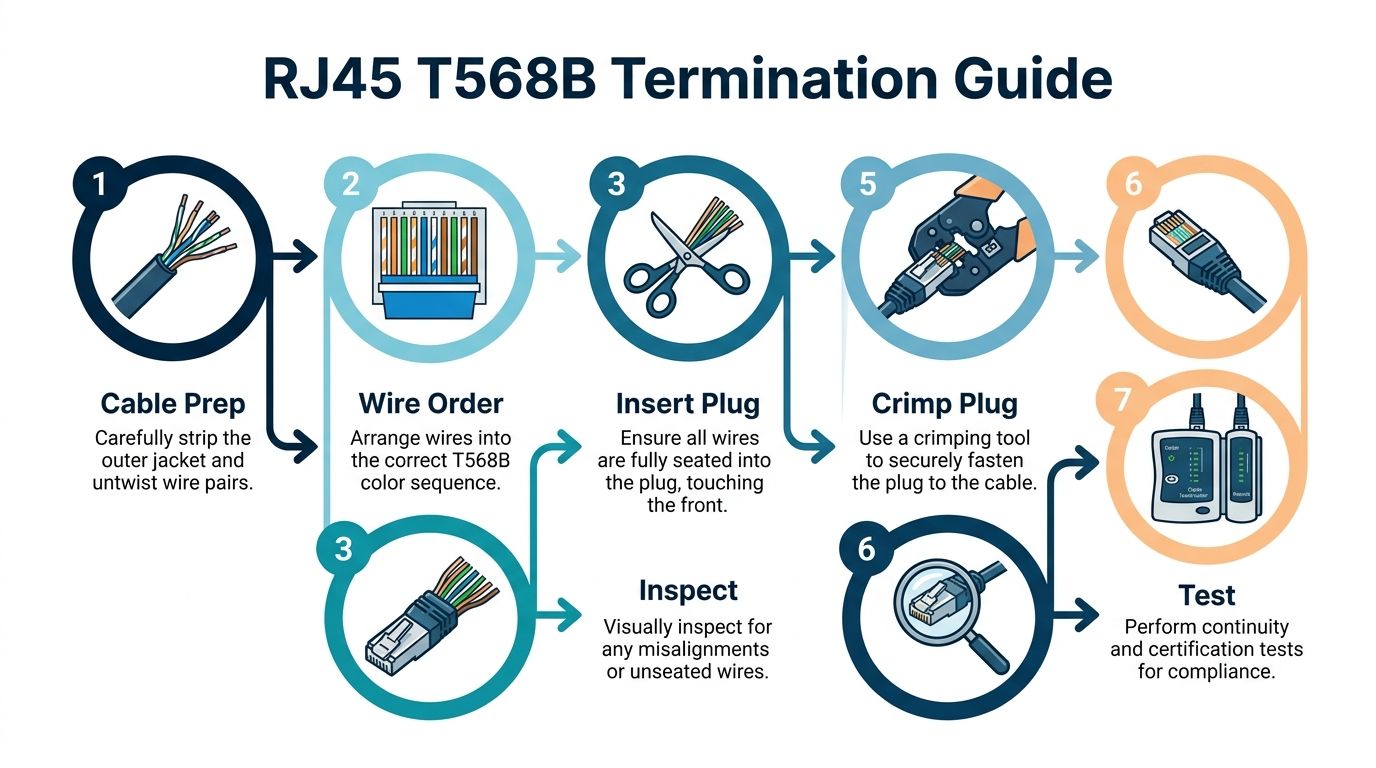
The Step-by-Step UK Termination Process T568B
A failed plug at handover can hold up an entire office floor. Desks are in, switches are live, the client wants users on by Monday, and one badly terminated lead starts dropping phones, printers or access points. That is why termination is treated as installation work, not bench tidying.
For UK structured cabling, the pinout needs to match the project standard and the rest of the installed estate. In commercial fit-outs, that normally means T568B, applied consistently and recorded properly so the link can be tested against the wider installation under BS EN 50173 and BS 6701. On managed projects, inconsistency here can also put manufacturer warranty cover at risk, particularly where approved components are mixed with site-made patching.
If the termination sits within a wider refurb or relocation, this UK office network wiring installation guide shows how plug work fits into the full cabling package.
Prepare the cable without disturbing the pairs
Strip back the outer jacket carefully with a proper cable stripper. Remove only enough sheath to dress the cores into the plug cleanly. If the blade marks the insulation, cut the end off and start again. It is quicker than fault-finding later.
Keep pair untwist to a minimum. Pair geometry is part of the cable's performance, so the conductors should stay twisted as close to the contacts as the plug design allows. Overworking the cores to make them look neat is one of the common reasons a plug looks fine and still fails under test.
Set the conductors in T568B order:
Pin 1 Orange-White
Pin 2 Orange
Pin 3 Green-White
Pin 4 Blue
Pin 5 Blue-White
Pin 6 Green
Pin 7 Brown-White
Pin 8 Brown
Check the sequence against the standard, not memory.
Trim, seat and crimp with the jacket captured
Once the conductors are straight and in order, trim them square so they enter the plug evenly. Uneven ends, crossed conductors or a core that folds back inside the nose will all give you an unreliable termination, even if continuity appears to pass.
Push the cores fully home and confirm all eight have reached the front of the plug. Then check the rear. The outer jacket needs to sit under the strain tab so the plug grips the sheath, not the individual conductors. In office work, leads get moved during furniture installs, cabinet dressing and post-handover churn. If the jacket is not captured, the termination will not last.
Use a ratcheting crimper and complete the cycle fully. Controlled pressure matters more than force. A rushed crimp can leave one pin partly set or fail to secure the cable jacket properly.
Before crimping, I check two things every time. Correct colour order at the front, jacket under the strain tab at the rear.
Inspect workmanship before the link goes to test
A close visual check catches a lot of failures before they reach the tester:
Confirm the colour order matches T568B exactly
Check all eight conductors are fully seated at the plug nose
Verify jacket capture under the strain relief
Reject damaged plugs or plugs with uneven conductor depth
Look for over-straightened pairs that have been untwisted too far back
This is basic workmanship control. It does not replace certification, but it does stop avoidable failures reaching the test stage.
Common site mistakes during fit-out work
The pressure points are predictable. Engineers often over-untwist the pairs to make insertion easier, or they trim badly and force the conductors into the plug. Both faults show up regularly on busy close-out periods where cabling, AV, CCTV and electrical teams are all working in the same space.
NHS rooms, meeting suites and shared office floors are unforgiving environments for this. A plug that only just works on the day can become an intermittent fault once patch leads are moved, cabinets are dressed tighter, or devices start drawing steady network traffic. Good terminations are not about getting the latch to click. They are about producing a link that will pass certification, support compliance, and stand up in service.
From Crimp to Certification Testing Every Connection
A plug isn’t finished when the crimper opens. It’s finished when the link passes certification and the result is recorded properly.
That distinction matters because many bad terminations look acceptable to the eye. The conductors appear in the right order. The pins seem seated. The latch is intact. None of that proves the link will behave correctly in service, especially on office floors carrying data, voice, CCTV or integrated building systems.

What the certifier is actually checking
The verified data for UK-compliant Cat 5 plug termination references testing with a Fluke DSX-5000 or similar and sets out these performance checks:
NEXT greater than 30dB at 100MHz
Attenuation below 24dB per 100m
Return loss greater than 16dB
Those numbers matter because they tell you whether the link is performing as a transmission path, not just whether electricity reaches the far end.
A continuity tester won’t give you that. It can tell you if the pairs map correctly. It won’t tell you whether the termination quality is good enough for compliant service.
Certification is about proof, not optimism
Professional installation lives on documentation. If a client, consultant or warranty provider asks whether the installed links were tested, “they all linked up” isn’t an answer.
The reason this becomes commercially important is simple. The verified guidance states that UK NHS fit-outs can mandate less than 2% re-termination rate for warranty compliance, with Excel Cat5e plugs used alongside a 25-year BS EN 50173 Class D guarantee. In other words, testing isn’t a nice extra. It sits directly inside the handover and warranty conversation.
Key point: Visual acceptance is a workmanship check. Certification is a performance check. You need both.
What works in practice
The most reliable workflow is to pre-certify plugs with a test fixture where possible, especially if you’re producing patch leads in batches. That catches obvious poor crimps before they end up in the cabinet or on the user floor.
Then certify the installed links properly and keep the results organised by outlet, cabinet and area. When faults appear later, that test history matters. It gives the IT team a baseline and stops everyone arguing over whether the cabling was ever right in the first place.
A disciplined testing process also supports operations in unmanned spaces. If a building relies on remote monitoring, access control and CCTV, the handover pack needs to show that the physical network was validated, not merely installed.
Why certification supports electrical and facilities teams too
This isn’t just an IT issue. Commercial electrical installation and certification increasingly overlap with data-dependent systems. Facilities teams expect remote door events, camera feeds and control traffic to work reliably after handover. When they don’t, the first few days of occupation become a blame exercise between trades.
A proper certification report cuts through that quickly. It tells everyone whether the copper path is compliant, where the defect sits and whether the problem belongs in the cable, the active equipment or the attached device.
Troubleshooting Common Cat 5 Plug Failures
A link can pass a quick wiremap in the comms room and still fail the moment staff move in, phones register, cameras come online and PoE starts drawing current. That is the point where poor plug work stops being a tidy cabling issue and turns into a warranty argument, a snagging delay, or a callout no one budgeted for.
On UK fit-outs, the repeat faults are usually basic workmanship problems. The pair order looks right at first glance, but the original pair relationship has been broken. The sheath is left too far back, so the strain tab grips conductors instead of jacket. The pairs are untwisted too far to make the plug easier to load, then the link struggles on crosstalk or return loss. In older office refurbishments and NHS estates, I also see mixed components, tired cable geometry and plugs chosen for convenience rather than compatibility with the cable type.
Faults that show up again and again on site
The same failure patterns keep turning up in commercial environments:
Split pairs. Continuity may pass, but performance does not. This is common where the installer has arranged cores by pin number instead of keeping the orange and green pairs intact to T568B.
Poor jacket capture. The plug may hold for handover, then start dropping out after patching, cabinet work or desk moves.
Uneven conductor trim or incomplete seating. One core stops short of the contact, or the pin does not bite cleanly through the insulation.
Too much untwist at the plug nose. The termination looks neat enough, but the pair geometry has already been disturbed.
Wrong plug for the cable. Solid conductor cable terminated into a plug intended for stranded patch cable is a common cause of intermittent faults.
Inferior plug bodies or worn crimp tools. Cheap consumables cost time later, especially on batch-made leads.
Those are the faults that matter in practice because they trigger retests, remedial visits and disputes over whether the installed cabling still meets the intended standard under BS EN 50173 and BS 6701.
Common RJ45 Termination Faults and Fixes
Failure Symptom (Tester Reading) | Likely Cause | Corrective Action |
|---|---|---|
Wiremap passes but certification fails on crosstalk | Split pair, often orange and green conductors placed in the right pin numbers but no longer kept as true pairs | Cut off the plug, sort by pair, and re-terminate to T568B with minimal untwist |
Open circuit on one conductor | Pin did not pierce insulation, or one core stopped short of the plug nose | Use a new plug, trim evenly, and confirm every conductor reaches the end before crimping |
Intermittent link when the lead is moved | Poor crimp or no proper jacket capture under the strain tab | Replace the plug and make sure the outer sheath sits inside the plug body and under the strain tab |
Return loss or impedance failure | Conductors left uneven, badly prepared, or forced into place after poor dressing | Re-cut square, trim consistently, and insert without buckling the conductors |
Failure after patching in the cabinet | Distorted plug body or mechanically weak termination | Replace with a better quality plug and check the crimper is still producing clean, even pin sets |
Older run will not support the expected service | Degraded cable geometry near the end, poor previous re-termination, or incompatible components | Re-terminate once properly, then test the full link to confirm whether the defect is local or in the fixed cabling |
How to diagnose the fault quickly
Start with the failure mode, not the tool in your hand.
If the tester shows a simple open, inspect seating and pin penetration first. If wiremap passes but performance fails, suspect split pairs or excessive untwist before anything else. If the fault appears only after patching or when the lead is disturbed, check jacket capture and plug compatibility with the cable construction.
A second failed re-termination on the same link is usually the point to stop remaking plugs and inspect the rest of the channel. In office refurbishments, the issue is often a damaged cable end, a crushed section above the ceiling, or a link assembled from mixed-category parts that should never have been signed off together.
Why this matters beyond the cabinet
Commercial clients do not judge the cabling by how tidy the plugs looked on day one. They judge it by whether phones stay up, access control reports cleanly, and support tickets stay low after occupation. A poor termination can undermine a reliable internet connection for communications, even when the WAN service itself is fine, because the failure sits in the last few centimetres of copper at the user end or in the cabinet.
That risk is higher in unmanned sites, shared offices and NHS environments where a failed link affects clinical devices, door controllers, CCTV, or remote monitoring. Good practice is simple. Use the correct plug for the cable, terminate once with proper pair control, and replace doubtful terminations instead of trying to save pennies on consumables. That approach protects performance, supports compliance, and gives the manufacturer or installer far less room to reject a warranty claim later.
Ensuring Network Integrity From Day One
The quality of a fit-out shows up in the boring places first. In labelled panels. In clean test results. In plugs that don’t need revisiting. That’s what keeps a building stable once people move in, systems go live and support calls start landing.
Cat 5 plugs sit right at that point where workmanship, compliance and operations meet. If the termination is poor, everything above it becomes harder to trust. If it’s done properly, tested properly and documented properly, the rest of the network has a solid foundation.
The wider building picture
That matters even more in mixed-use and unattended environments. Unmanned building projects usually fail when the design team treats access control, CCTV, electrical installation and data cabling as separate workstreams instead of one operating system. A remote site only feels autonomous when the infrastructure underneath is coordinated.
A practical design approach ties together:
Access so authorised users can enter without ad hoc workarounds
Power so connected devices stay stable and maintainable
Data so monitoring, control and communications remain dependable
Maintenance so facilities teams aren’t burdened with constant callouts
Battery-less NFC proximity locks often make sense in those settings because they remove routine battery replacement from the maintenance list. That’s a real operational advantage for dispersed properties, managed units and low-footfall buildings. But the lock choice only pays off if the surrounding cabling, CCTV connectivity and handover standards are equally well planned.
For teams also reviewing voice and remote services, this note on the importance of a reliable internet connection for communications is a useful reminder that the WAN matters too. Internal cabling and external connectivity have to support each other.
If you're planning an office relocation, fit-out, cabling refresh or an autonomous building environment and want the infrastructure done properly from first fix through certification, Constructive-IT can help you design, install and hand over a network that’s compliant, supportable and ready for real-world use.