

You're probably looking at a floor plan, a relocation deadline, and a pile of disconnected requirements. Wi-Fi coverage. Door access. CCTV. Network cabinets. Electrical works. Maybe a smart meeting room rollout. Maybe a building you want to run with minimal on-site staff. On paper those look like separate workstreams. In practice, they fail together.
That's why a mesh network diagram matters far beyond Wi-Fi. In a commercial fit-out, it's the drawing that tells you whether laptops roam cleanly, whether CCTV stays online, whether access events reach the controller, and whether the building can operate as an unmanned site instead of needing someone to drive over every time a switch, lock, or router misbehaves.
A lot of diagrams stop at “put an access point here”. That's where projects start going wrong. A usable diagram for a new office fit-out has to show the relationship between wireless nodes, wired backbone, power, access control, cabinet locations, and failure points. If it doesn't, you don't have a network plan. You have a sketch.
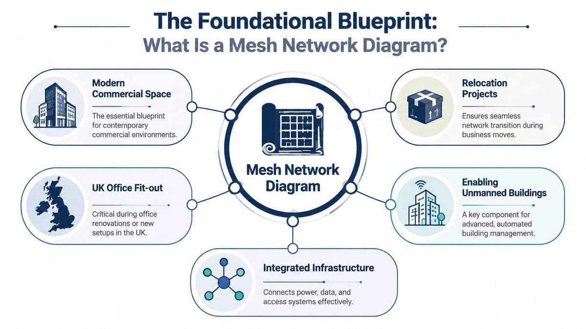
What Is a Mesh Network Diagram
A mesh network diagram is the operating blueprint for connectivity across the building. It shows where each node sits, how traffic moves between them, which links are wireless, which are wired, and where the gateway or root connection lives. In a UK office fit-out, that drawing should sit alongside your floor plan early, not after furniture, ceilings, and partitions are already fixed.
What the diagram actually needs to show
At minimum, a business-grade mesh diagram should identify:
- Gateway location. The point where the network roots back to the core connection or switching stack.
- Node positions. Not just “one per floor”, but exact intended placements relative to walls, risers, ceilings, and working areas.
- Backhaul paths. The critical distinction between wireless backhaul and wired backbone links.
- Service dependencies. CCTV, access control, VoIP, occupancy sensors, and anything else that stops working when the network stumbles.
That last point is usually missed. A mesh network diagram isn't only about user Wi-Fi. In a modern office, it underpins building services.
Why this matters during fit-out
By the time a contractor has closed ceilings and the furniture team has dropped in steel storage, your RF environment has changed. If the only plan was a generic Wi-Fi layout, you'll end up moving access points, adding unscheduled cabling, or accepting dead patches that hit users and systems alike.
Practical rule: If the diagram doesn't help facilities, electrical, and security teams make decisions, it's too narrow for a commercial project.
The drawing also gives the IT manager a way to challenge assumptions early. If a proposal relies heavily on wireless-only links across multiple rooms and floors, the problem is visible before anyone starts drilling.
Here's the practical distinction. A domestic mesh diagram is mostly about coverage. A commercial mesh network diagram is about coverage, resilience, maintainability, and service continuity. Those are not the same thing.
| Element | Home-style diagram | Commercial fit-out diagram |
|---|---|---|
| Main goal | Wi-Fi reach | Operational reliability |
| Backhaul detail | Often omitted | Must be explicit |
| Power planning | Rarely shown | Essential |
| Access and CCTV impact | Usually ignored | Must be included |
| Failure planning | Minimal | Required |
If you're planning a relocation or a new floor, treat the mesh network diagram as a project control document. It tells you where the weak points are before they become expensive ones.
Key Topologies and Diagram Components
Calling every multi-AP layout a mesh is how bad fit-outs get approved. For an office move or new floor, the diagram needs to show what is meshed, what is wired, and what fails over when a link drops. If that is vague on the drawing, it will be vague on site.

Full mesh versus partial mesh versus hybrid mesh
A full mesh gives every node a direct path to every other node. Engineers like it in theory because it removes single points of failure between nodes. In commercial offices, it becomes expensive fast, hard to document properly, and awkward to troubleshoot once other building systems sit on top of it.
A partial mesh gives extra paths only to the nodes that matter most. That usually fits real buildings better. Comms rooms, core switches, door controllers, and uplinks can have redundancy, while low-risk edge devices keep a simpler path.
A hybrid mesh is the design we specify most often for fit-outs with smart building ambitions. The wired backbone carries the traffic that cannot tolerate instability. Wireless links fill the awkward areas where cabling is disruptive, slow to install, or poor value. That balance matters if the building is expected to keep access control, CCTV viewing, sensors, and user connectivity running without constant hands-on support.
One warning. A wireless backhaul that looks fine during a survey can behave very differently after ceilings, partitions, glazing, and furniture go in.
If a proposal shows "mesh everywhere", ask which services share each backhaul link and what the fallback path is when one node loses power or RF quality drops.
The components that belong on the drawing
A usable mesh network diagram has to do more than show coverage blobs. It should let the IT manager, electrician, and security contractor answer the same practical questions from one sheet.
Core items to include
- Gateway node. Show the handoff into the switching core and internet edge.
- Satellite nodes. Label which nodes are leaf nodes and which ones carry transit traffic for others.
- Backhaul type. Mark each uplink as wired or wireless. Installers should not have to guess.
- Controller or management platform. Identify where management lives and how remote access is provided.
- Power method. If devices are fed by Power over Ethernet for access points and edge devices, show that on the drawing with the serving switch or injector location.
- Critical services. Include door controllers, CCTV endpoints, sensors, riser cabinets, comms rooms, and any cabinet that supports life-safety or operational systems.
- Failure boundaries. Mark what drops if a node, switch, or cabinet goes offline.
That last point gets missed often. If one cabinet failure takes out Wi-Fi, cameras, and door events for half a floor, the diagram should make that obvious before procurement starts.
Placement guidance that affects the drawing
Placement rules need context. Open-plan desks, cellular offices, meeting rooms with acoustic glass, and stair cores all behave differently, so the diagram should reflect the building fabric rather than a generic vendor template.
For UK office fit-outs and multi-storey relocations using hybrid mesh layouts, a common starting point is to place the gateway in a central, high position and space satellite nodes at roughly 12m to 15m in open areas, reducing that to 7.6m to 9.1m where walls and partitions interfere with signal (Deals on Broadband mesh Wi-Fi systems guide).
Treat those figures as planning prompts, not fixed design rules. Metal storage, lift cores, mirrored finishes, and dense ceiling services can all change the result. I have seen drawings that looked tidy on paper fail badly once joinery and occupancy were in place.
What usually works in practice
For most serious office projects, the safest pattern is clear. Keep wired links for busy areas, shared services, and anything tied to building operations. Use wireless mesh links where they solve a real installation problem, not as a shortcut for the whole floor.
In practical terms:
- Full mesh suits specialist environments more than standard offices.
- Partial mesh works where a few nodes need protected paths.
- Hybrid mesh usually gives the best balance of resilience, cost control, and maintainability.
A finished diagram should show more than connectivity. It should show which failures are merely inconvenient and which ones stop the building from functioning as intended.
Integrated Planning for Power Data and Access
A new office fit-out often looks fine until handover week. The doors open, the Wi-Fi appears to work, cameras are online, and then the snags start. Access events fail to reach the management platform. A switch reboot drops CCTV on one side of the floor. An electrical isolation takes out a cabinet feeding both door controllers and wireless nodes. None of those failures begin with the mesh. They begin with separate design packages that were never coordinated.

For an unmanned building, the mesh network diagram has to do more than show coverage. It needs to show how connectivity, electrical supply, and access control stay live together under normal load, during maintenance, and after a single fault. That is the difference between a tidy network drawing and a building that can run without constant site visits.
Why siloed design causes expensive faults
Commercial projects still get split into separate scopes. The access contractor marks doors and readers. The electrical contractor marks supplies and containment. The IT team marks cabinets, switches, and APs. By the time those drawings meet, the risers are crowded, the cabinet power is wrong, and nobody has owned the link between a door event and the network path that carries it.
That gap matters because fault tolerance is now a standard requirement in smart building automation, not a nice extra, as noted earlier in the article. The problem is that many diagrams still stop at wireless placement and ignore the dependencies that make the system usable day to day.
The failures are predictable:
- Doors open locally but events fail upstream because the controller path is unstable or poorly segmented.
- CCTV records on site but remote teams cannot view it because uplinks, QoS, or switch resilience were never defined.
- APs are mounted where they look neat on a reflected ceiling plan rather than where cabling routes, power, and RF conditions support steady service.
- Planned electrical works knock out operational systems because comms equipment was left on the wrong circuit or without the right protection.
Those are building operation problems, not just IT problems.
Draw three service layers on one plan
The cleanest way to prevent rework is to keep power, data, and access on the same coordinated drawing set. Separate documents are still useful for specialist detail, but the decision points need to be visible together.
Layer one: data
Mark cabinet positions, fibre or copper backbone routes, patching points, switch locations, uplinks, and APs. Show which devices rely on wired backhaul and which can tolerate a wireless hop. If a route crosses a riser, ceiling service zone, or fire compartment, mark that too. Installers need to know where the path is likely to fail before the first cable is pulled.
Where the fit-out needs extra containment or cabinet capacity, tie the network design to a proper structured cabling plan for the office fit-out. Leaving that decision until late usually leads to exposed cabling, overloaded cabinets, or last-minute compromises on AP and controller locations.
Layer two: power
Show how each switch, AP, camera, controller, and edge device is powered. Some endpoints will sit happily on PoE. Others need local power, lock power supplies, or controlled shutdown. The diagram should also show which equipment shares a circuit, what stays up on backup power, and what can be taken offline for maintenance without affecting access or visibility.
Projects frequently run into trouble. A single cabinet may feed Wi-Fi, CCTV, and door hardware. If that cabinet has no power resilience, one small electrical issue becomes a building-wide support call.
Layer three: access
Access control should sit on the same design logic as the network. Mark readers, controllers, door interfaces, fail-safe or fail-secure behaviour, and the route back to the switching layer. If the building relies on remote support, show the management path as clearly as the door itself.
One site issue comes up repeatedly. The lock hardware is installed correctly, but the support path is weak or undocumented. The result is a door that works physically yet fails operationally because alarms, logs, or remote commands do not reach the right team.
Battery-less NFC locks reduce one problem, not the rest
Battery-less NFC proximity locks make sense in many unmanned spaces because they remove a steady maintenance task. That helps in satellite offices, shared commercial suites, plant spaces, and other locations where routine battery changes are easy to miss.
The trade-off is straightforward. Lower door maintenance does not reduce the need for sound infrastructure around the door. It increases the need for it. If the building depends on remote management, then controller uptime, switch resilience, event logging, and network visibility matter more than ever.
That is why the mesh network diagram should be treated as part of the building operating model. It needs to show how people get in, how systems stay powered, how events reach the right platform, and what happens when one component fails.
One option in this kind of joined-up delivery is Constructive-IT, which plans and installs network infrastructure alongside electrical works, CCTV, structured cabling, and fit-out support for office relocations and new commercial spaces.
The Mesh Network as a Smart Building Foundation
When people say they want an unmanned building, they often mean “we want fewer site visits”. That's part of it, but it's too vague to be useful in design.
In UK practice, unmanned building management means the property automates core functions such as access, security including CCTV, utilities, and environment so it can operate without permanent on-site staff. Day to day, the system has to answer four operational questions remotely: who can enter, what's happening inside, whether critical systems are powered and connected, and whether remote diagnosis or action is possible (Constructive-IT guide to unmanned building management).
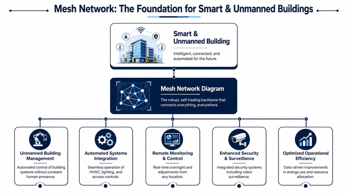
If your mesh network diagram doesn't support those four questions, it isn't supporting an unmanned building. It's only supporting Wi-Fi.
What these buildings look like in the real world
Common examples include:
- Multi-tenant office suites where doors, shared areas, and comms need remote oversight
- Satellite offices that don't justify full-time on-site operations staff
- Industrial or utility spaces where building services need monitoring without permanent presence
- Converted office properties with external areas where indoor and outdoor connectivity both matter
- Healthcare and compliance-sensitive environments where reliability matters across access, CCTV, and environmental monitoring
In these settings, network reliability is often the hidden dependency. Users may notice poor Wi-Fi. Operators notice something worse. Event logs stop updating, camera streams drop, door actions become harder to verify, and support staff lose confidence in remote decisions.
Why many unmanned building projects fail
They usually don't fail because the concept is wrong. They fail because the implementation treats systems as separate purchases.
A building marketed internally as “autonomous” often still depends on someone visiting site when:
- the network cabinet loses power,
- a wireless uplink becomes unstable,
- a camera can't be reached remotely,
- a door event isn't recorded,
- or no one can tell whether the fault sits with access control, switching, internet connectivity, or local power.
That is not unmanned operation. That is deferred troubleshooting.
Here's the practical test. If a routine issue forces a site visit because nobody can remotely see power state, network status, or access history, the building isn't properly unmanned.
The network is the shared dependency
A resilient mesh network design is what ties together:
- CCTV, so footage and live views remain available
- Access control, so authorisation and audit events stay visible
- Environmental and utility monitoring, so teams can see what the building is doing
- Remote support, so faults can be diagnosed without sending someone out first
For planning purposes, that means the mesh network diagram has to include service paths and likely failure points, not just node icons.
A proper survey matters here. If you're validating coverage and signal behaviour before or after installation, Wi-Fi coverage mapping helps expose where design assumptions and real building conditions diverge.
A short visual overview helps if you're aligning IT and facilities around the same outcome:
Maintenance is part of the design, not an afterthought
The more autonomous the building, the more disciplined the maintenance model needs to be.
| Operational area | What needs planning |
|---|---|
| Access control | Credential lifecycle, audit review, remote unlock procedures |
| CCTV | Storage checks, remote viewing validation, camera health monitoring |
| Network | Firmware control, alerting, switch health, backhaul visibility |
| Power | Protected supplies, outage visibility, restart procedures |
| Compliance | Installation records, certification, test evidence, change logs |
A tidy handover pack doesn't keep a building running. Clear fault visibility, labelled infrastructure, and tested recovery paths do.
Many “smart building” projects lose credibility when the hardware is modern but the support model is still manual. If the mesh network diagram has done its job, maintenance becomes predictable because dependencies are visible before the system goes live.
From Diagram to Certified Installation
A clean design drawing doesn't guarantee a reliable result. The building still has to be installed, tested, labelled, and certified properly. That matters even more when you're building out a fully autonomous unmanned building unit, because faults don't stay confined to IT. They spill into security, operations, compliance, and facilities.
What professional execution changes
The installation stage is where trade-offs become physical. Cable routes compete with ceilings and containment. Access point positions run into steelwork, ducting, or awkward wall construction. Door hardware introduces dependencies on both electrical installation and network pathing. If the team on site isn't working to a joined-up design, the original diagram gets diluted one “small change” at a time.
The wireless side has hard limits that should shape deployment choices. In UK dual-radio wireless mesh environments, standards set a maximum of 1 to 2 mesh hops to avoid capacity degradation and call for a minimum SNR of 25dB for reliable backhaul performance. The same guidance notes that thick brick walls in UK buildings can drastically reduce effective signal range (Ruckus wireless mesh best practices).
That's why experienced teams don't treat wireless mesh as a substitute for proper cabling. They use it selectively.
Certified installation is not paperwork for its own sake
Commercial electrical installation and certification matter because building systems are interconnected. An AP mounted neatly but fed from the wrong electrical arrangement can still undermine the project. A lock controller on an undocumented circuit can still create support risk. A cabinet with poorly terminated links can still pass a visual check and fail under load.
A proper deployment should include:
- Structured cabling installed to standard with test results and labels
- Commercial electrical works signed off correctly so power arrangements are safe and documented
- Wireless validation on site so the physical building matches the intended design
- Service commissioning across CCTV, access, switching, and remote monitoring
- Handover evidence that support teams can effectively use later
What usually undermines the project
The recurring problems are familiar:
- installers shifting APs for convenience rather than design intent
- access systems added after the cabling routes are closed
- wireless backhaul stretched through materials that kill signal quality
- no clear separation between user traffic and operational building services
- no meaningful test of what happens when a device, link, or circuit fails
Commission the building like an operational system, not a collection of products. If one trade signs off without proving interoperability, the risk hasn't gone away. It's just been moved to go-live day.
For fit-outs where uptime matters, certification isn't admin. It's the evidence that the building can support the way you intend to run it.
Your Checklist for a Resilient Network Blueprint
If you're reviewing a fit-out, relocation, or smart building project, use the checklist below before any final installation decisions are locked in. It will catch most of the mistakes that lead to patchwork fixes later.
Start with the operating model
Before choosing topology, answer the building question. Is this just office Wi-Fi, or is the site expected to support unmanned operation, CCTV, controlled access, and remote diagnostics?
If the answer includes autonomous or low-touch operation, the diagram has to reflect building services, not only user coverage.
Check the topology against the building
Use this as a review filter:
- For dense commercial areas. Prefer a hybrid approach with wired backbone where service continuity matters.
- For selective resilience. A partial mesh may be acceptable if you're clear about which nodes are critical.
- For proposals heavy on wireless-only links. Challenge the backhaul assumptions and ask where performance falls away first.
Review placement and dependency detail
A usable mesh network diagram should let you verify:
- Where the gateway sits and why
- How each node uplinks
- Which services depend on each path
- What loses connectivity if one node or cabinet fails
If those answers aren't obvious from the drawing, it needs more work.
Confirm power, access, and CCTV are on the same plan
This is the part many teams skip.
Ask these questions directly
- Are APs, switches, cameras, and controllers shown with their power method?
- Do door systems appear on the same coordinated drawing as network infrastructure?
- Has CCTV been designed as an operational service, not a bolt-on?
- Are electrical works and network works sequenced so neither compromises the other?
A mesh network diagram that ignores those items usually produces support issues later.
Test for maintainability, not just installation
Use a short acceptance table when reviewing supplier designs:
| Review point | What good looks like |
|---|---|
| Fault visibility | Remote teams can identify whether the issue is power, network, or access related |
| Documentation | Labels, test records, and cabinet schedules are complete |
| Service recovery | There's a defined path to restore critical systems without guesswork |
| Expansion | The design allows later additions without ripping up the core layout |
Choose suppliers who can deliver the whole chain
For a critical fit-out, ask whether the delivery team can handle network design, cabling, Wi-Fi validation, CCTV integration, access coordination, and commercial electrical certification in one managed programme or whether you'll be left stitching multiple contractors together yourself.
That question often tells you more than the quote.
If the site only needs basic coverage, a simple design may be enough. If the building needs to run reliably with limited on-site intervention, the mesh network diagram has to become a full infrastructure blueprint.
If you're planning a fit-out, relocation, or an unmanned building project where downtime isn't acceptable, it's worth having Constructive-IT review the network, power, and access design together before installation starts. That usually saves far more trouble than trying to correct the building after handover.