

You're probably in the middle of a fit-out, relocation, or server room upgrade where every decision is now connected to everything else. The access control vendor wants final door schedules. The CCTV contractor needs power points and comms routes. The electrical team wants load figures locked down. IT wants assurance that a mains failure won't drop core services on day one.
That's where a UPS sizing calculation stops being a spreadsheet exercise and becomes a project risk decision.
In older sites, getting the UPS slightly wrong often meant a messy shutdown and a lesson learned. In modern automated facilities, especially unmanned units, the consequences spread further. If power drops, you don't just lose servers. You can lose remote access, surveillance visibility, environmental monitoring, and the ability to manage the site without sending someone out.
Why Your UPS Sizing Calculation Is More Than Just a Number
A common mistake is treating UPS sizing as a quick conversion from watts to kVA, then picking the next model up. That approach looks efficient during procurement and causes trouble during commissioning.
Incorrect sizing isn't a fringe issue. Common pitfalls in UPS sizing include underestimating non-linear load impacts, neglecting crest factor considerations, and failing to incorporate future growth margins. Those errors lead to 30–40% of UPS failures in UK commercial environments according to this industry analysis on UPS sizing pitfalls.
Why the calculation now affects the whole building
In a conventional office, a UPS may support a server rack, a few switches, and telephony. In an automated building, the protected load often extends into operational technology. That includes door controllers, edge networking, remote utilities interfaces, CCTV recording or analytics, and supporting comms.
If those systems are meant to keep the building running without on-site staff, the UPS becomes part of the operating model, not just the electrical design.
Practical rule: Size the UPS around what must stay controllable during a fault, not just what feels important in the rack.
What many teams get wrong
The failure usually starts with a false assumption. Someone uses nameplate figures, ignores startup behaviour, assumes the battery runtime on a datasheet applies to the actual connected load, and leaves no room for expansion. The result is familiar:
- The inverter trips on switching events because crest factor and inrush weren't checked.
- Battery runtime collapses under real load because the design used ideal figures.
- Access, data, and power get designed separately so one critical subsystem falls outside UPS protection.
- The site passes handover but fails in operation because nobody tested it as an integrated environment.
A proper UPS sizing calculation answers a harder question. Not “what box do we buy?” but “what has to remain live, for how long, under what conditions, and with what recovery path?”
That's the right starting point for critical facilities and fully autonomous unmanned building units.
First Principles Assessing Your True Power Load
A reliable calculation starts with a load audit. Not a guess. Not a vendor brochure. An actual list of every connected item that must remain powered.
The right method is simple in principle and detailed in practice. A recognised engineering approach begins by determining all connected loads by tabulating equipment with power ratings in Watts or VA as the first step in a four-step UPS sizing process, as outlined in this UPS sizing methodology reference.
Build the load list from the site, not from memory
Walk the design package and create a schedule that includes:
- Core IT equipment such as servers, storage, firewalls, routers, switches and console devices
- Security systems including CCTV cameras, NVRs, access control panels, intercoms and door hardware interfaces
- Building support systems such as remote monitoring gateways, environmental sensors and comms cabinets
- Control dependencies like PoE switches feeding cameras and door readers, because a small switch failure can take down a large part of the site
For expansion projects, this is also where data centre capacity planning matters. A UPS sized only for today's rack count is usually undersized before the project has settled into normal operations.
Watts, VA and power factor
Often, many spreadsheet calculations drift off course.
Watts are the actual power your equipment uses. VA is apparent power. UPS systems are often rated in VA or kVA, so if you only total watts and ignore power factor, you can select a unit that looks adequate on paper but isn't.
For modern equipment, power factor is often reasonably high, but not every load behaves cleanly. Switch-mode power supplies, PoE-heavy network estates, and mixed security hardware can create a less tidy load profile than the rack labels suggest.
A practical approach:
| Measure | What it tells you | Why it matters |
|---|---|---|
| Watts | Real consumed power | Used for energy and runtime thinking |
| VA | Apparent electrical demand | Used for UPS capacity selection |
| Power factor | Relationship between the two | Affects conversion from watts to VA |
Nameplate ratings are a starting point, not the answer
Manufacturer ratings are useful for a first pass, but they often represent maximum draw, not normal operation. Sometimes that causes oversizing. In other cases, it hides more important behaviour such as transient demand, load peaks, or clustered startup events.
What works better is a layered approach:
- Use the design inventory to capture all intended connected equipment.
- Check datasheets for watts, VA, input current, and any startup behaviour.
- Measure where possible on existing loads using PDU data, metering, or temporary test equipment.
- Separate must-stay-live loads from nice-to-have loads so the UPS protects continuity, not convenience.
If you can't explain exactly why a device is on the UPS schedule, it probably shouldn't be there.
That discipline matters in unmanned environments. A forgotten CCTV switch, a door controller on the wrong circuit, or a remote comms gateway left off the protected side can break the whole operating model even when the main UPS is technically “working”.
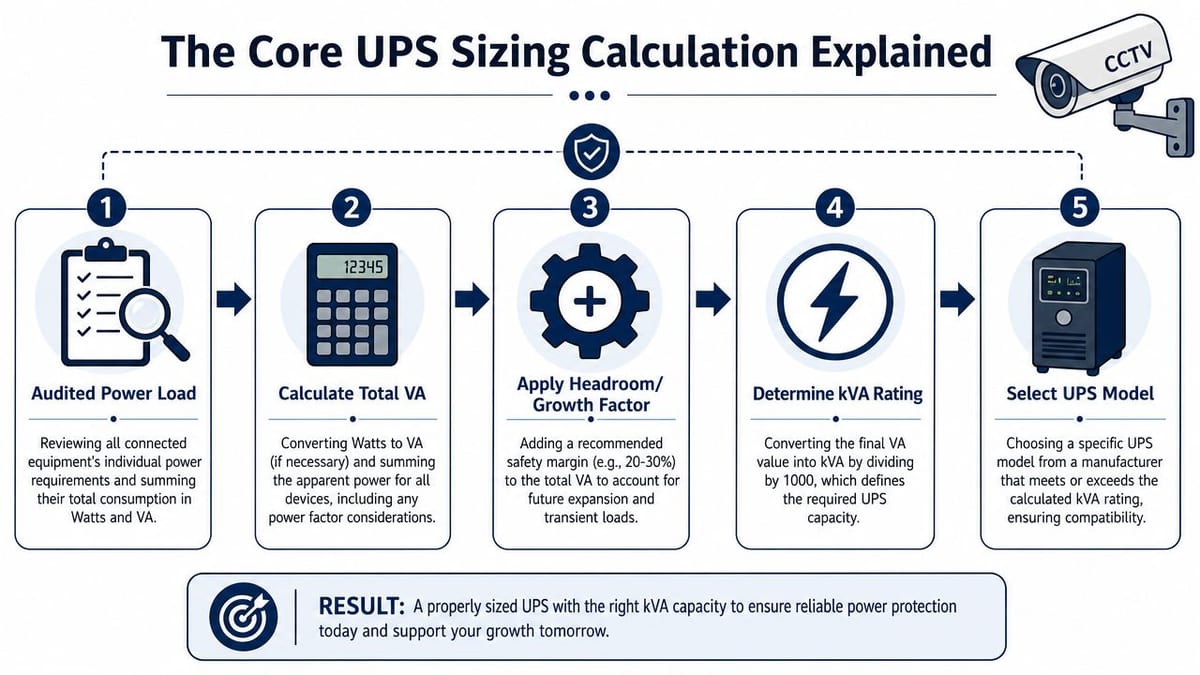
The Core UPS Sizing Calculation Explained
Once the audited load is clean, the UPS sizing calculation becomes much more straightforward. The job is to convert the actual site requirement into a UPS capacity that can cope with present demand, switching behaviour, and planned growth.
Start with the design load
Take your protected load total and convert it properly. If some devices are listed in watts and some in VA, normalise the schedule so you can see both the actual load and the apparent load clearly.
Industry best practice for UK data centres is to operate UPS systems at about 80% of rated capacity, with a 20% safety factor or headroom added to total power draw so the system can manage peak load and future growth, as explained in this UK UPS sizing best practice guide.
That guidance is practical because it reflects how real sites behave. Loads drift upward. Extra switches appear. CCTV storage grows. A spare cabinet turns into an active cabinet faster than anyone planned.
A workable example
Say your audited protected IT and building systems load comes to 200 kW. The best-practice method in the source above uses an expected growth factor, then adjusts for power factor, then adds headroom.
In plain terms, the sequence is:
- Take the current protected load
- Apply expected growth
- Adjust for power factor to get apparent demand
- Add safety headroom
- Select a UPS that will run at around 80% loading in normal operation
That last step matters. If your normal operating load sits too close to the UPS rating, small changes in demand can create overload risk. If you oversize wildly, you can waste budget, floor space, and efficiency.
What the paper calculation often misses
The clean kVA answer is only part of the job. You still need to check whether the UPS can handle how the load behaves.
Use this checklist before freezing the model selection:
Non-linear loads
Server and network power supplies don't draw current in a perfectly smooth way. That affects UPS performance and waveform handling.Crest factor
The inverter has to support current peaks, not just average demand. This matters for switch-mode power supplies and concentrated IT loads.Inrush current
Startup events can be brief and still cause trouble. UK UPS design practice also accounts for start-up in-rush demands that can last up to 100 milliseconds in the referenced sizing guidance above.Largest single switching event
If a major device or load bank comes online suddenly, the UPS must ride through it without voltage dip that resets other equipment.
A UPS that supports the steady-state load but falls over on a switching event is still undersized.
Selection is a system decision
After the capacity maths, choose the actual UPS model based on installation reality. Check footprint, battery architecture, bypass arrangement, service access, and integration with monitoring and alarms.
For smaller residential backup projects, the thinking is different, but the logic of matching power demand to practical continuity still applies. A useful comparison point is this guide to Brisbane home power solutions, which shows how backup design changes when the objective is selective resilience rather than full commercial continuity.
In critical commercial environments, though, the best choice is usually the unit that gives you enough headroom, clean integration, sensible maintenance access, and a realistic expansion path. Not the unit that just about passes the spreadsheet.
Sizing Batteries for Real-World Runtime and Outages
A battery runtime target is an operational decision before it is a formula.
If an unmanned facility loses mains at 2 a.m., the question is not whether the UPS rating looked correct on a submittal. The question is whether access control, CCTV, networking, remote alarms, and the systems needed for recovery stay alive long enough for the site to protect itself. That is why battery sizing sits squarely inside business continuity and risk planning, not just electrical design.
Runtime should follow the operational plan
Set runtime from the actual outage response model.
A site that shuts down cleanly after a controlled sequence needs one answer. A generator-backed site needs enough battery autonomy to cover start delay, transfer time, and any failed-start contingency. An unmanned building usually needs more margin because there is no operator in front of the rack to shed load, acknowledge alarms, or restart failed edge devices.
UK grid performance also varies by location and weather exposure, so copying a standard autonomy figure across every project is poor practice. The UK government's electricity interruption reporting and resilience data at gov.uk energy and power interruptions information is a better reference point than a generic runtime calculator when you are setting assumptions for outage planning.
The battery formula gives you a starting point
Most battery sizing starts with stored energy:
Wh = Total Load (W) × Desired Runtime (h)
That gets you to a first-pass number. It does not give you a deployable design on its own. Real battery sizing also has to account for inverter losses, battery ageing, ambient temperature, discharge limits, and the fact that manufacturers rate batteries under specific test conditions that rarely match a live plant room or comms cabinet.
I usually treat the calculated watt-hours as the floor, then add margin based on the site's maintenance regime and response model. A site with generator support, tested monthly and attended quickly, can accept a tighter design than an unmanned building that depends on remote visibility and third-party callout.
For those remote sites, monitoring is part of the battery strategy. If you cannot see cabinet temperature, humidity, battery alarms, and room conditions remotely, your autonomy model is only true on paper. Environmental monitoring for critical spaces should sit alongside battery design, because heat and unnoticed alarm states shorten runtime long before a discharge test makes the problem obvious.
A short explainer helps visualise why runtime planning gets tricky in practice:
High discharge rates change the result
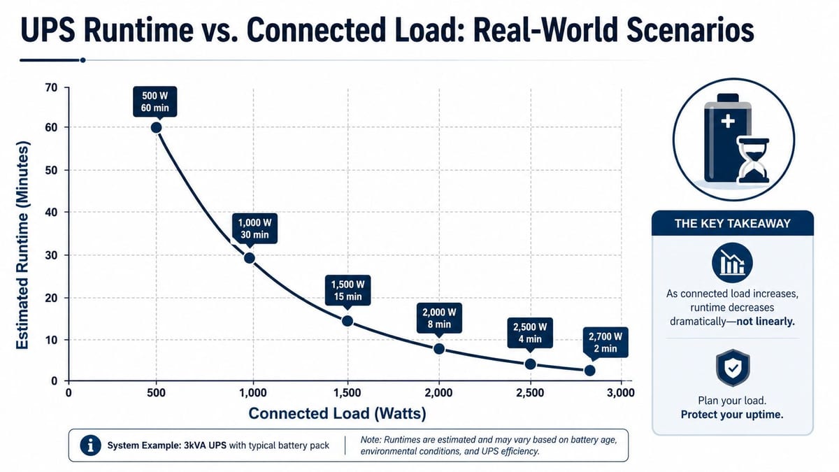
Battery discharge is not linear.
The practical effect is simple. Higher current draw reduces available capacity, so a battery string that appears adequate at a modest load can miss the runtime target once dense PoE switching, video recording, access control, and core network loads all stay online together. This catches designers who size autonomy from nominal battery data without checking the manufacturer discharge tables for the actual runtime window.
Heat makes the problem worse. So does age. A battery bank that meets the target on day one may miss it near end of life unless you leave margin for degradation and realistic room conditions.
Battery runtime on a brochure is not the same as runtime in a live rack with heat, ageing and real current draw.
Practical battery decisions
A battery plan is easier to trust when it answers operational questions early:
| Question | What to decide |
|---|---|
| How long must the site stay functional? | Until shutdown, generator takeover, or engineer attendance |
| What must stay up first? | Core network, CCTV, access control, remote management |
| What can drop early? | Non-critical loads that consume battery unnecessarily |
| What happens at end of battery life? | Keep enough margin so the runtime target still holds before replacement |
| Who depends on the protected systems staying live? | Security, facilities, remote operators, and external monitoring teams such as Amax Fire & Security for data centers |
The expensive mistake is assuming battery autonomy is just a longer version of the UPS kVA calculation. It is a risk decision about how the building behaves during a real outage, under real temperature, at real battery age, with no one on site to improvise.
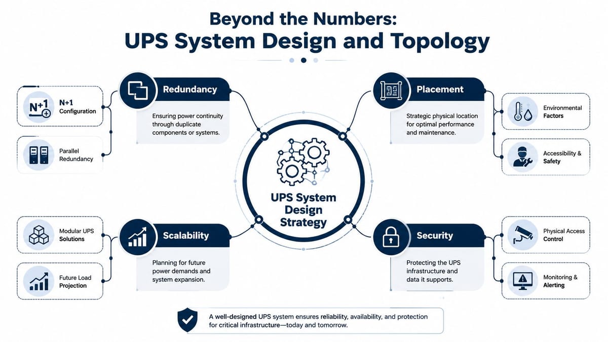
Beyond the Numbers System Design and Topology
A UPS doesn't protect a building on its own. The surrounding design does that.
What unmanned building management means in practice
In practical terms, unmanned building management means automating core property functions through digital-key access control, AI-powered CCTV for real-time activity flagging, and remote utilities management so day-to-day operation doesn't require on-site staff, as described in this guide to unmanned building management.
That definition matters because it changes how you size and place protected power. If the building depends on remote access and surveillance to function, those systems aren't peripheral. They're operationally critical.
Why many unmanned building projects fail
Most failures come from siloed design.
The access control package is specified first. CCTV follows. Networking gets fitted around both. Electrical design then protects the obvious IT rack but not every dependency that makes the autonomous model work. On paper, all systems exist. In operation, they don't survive together.
Common failure patterns look like this:
- Doors stay secure but remote management drops, so nobody can grant or revoke access reliably.
- CCTV cameras stay powered but the recording path fails, so the site is blind when footage is needed.
- The network survives but field hardware doesn't, because local power injectors or controllers weren't on protected circuits.
- Remote utilities exist without resilient comms, so operators can't see the actual state of the building.
Access, power and data have to be designed together
In automated sites, these three layers are one system.
A door event becomes data. That data depends on network transport. The network depends on power continuity. CCTV verification depends on the same chain. If one leg is fragile, the autonomous model breaks.
That's why comms design has to sit beside electrical design from the outset. Wireless may suit some sensor and mobility layers, but core resilience still depends on solid fixed infrastructure. This is especially relevant when planning the split between wired resilience and radio coverage in Ethernet and wireless building networks.
Why battery-less NFC proximity locks make sense
For unmanned units, battery-less NFC proximity locks solve a real operational problem. Battery-powered door hardware creates a hidden maintenance estate. Someone has to track battery life, replace cells, respond to failures, and prove that every opening point remains reliable.
Battery-less NFC hardware avoids that recurring burden. It also reduces the chance that a local lock battery becomes the weak point during a broader power or communications event. In practice, that gives operators fewer silent failures to chase across dispersed sites.
That's one of the strongest design choices for autonomous suites, managed workspaces, plant rooms, remote comms rooms, and multi-tenant service areas where regular manual checks are hard to justify.
Topology, certification and physical delivery
Resilience still comes down to architecture. Some sites accept a simple design. Others need redundancy in the UPS path, bypass arrangements, or segmented protection for separate services.
The right answer depends on the consequence of failure, but these checks are universal:
- Commercial electrical installation and certification must match the final protected load and fault strategy.
- Cable routes and containment need to support both power and data without creating service bottlenecks.
- CCTV and access control should be included in protected load reviews, not added after commissioning.
- Maintenance access has to be built in, especially where battery changes, lock servicing, or UPS bypass operations will happen in live environments.
For facilities with high security requirements, physical system design also benefits from specialist guidance such as Amax Fire & Security for data centers, particularly where access control, CCTV coverage, and resilient monitoring have to align with the wider infrastructure strategy.
Typical use cases include data centres, NHS estates, managed offices, logistics units, high-value storage facilities, remote plant spaces, and commercial buildings being built out as fully autonomous unmanned building units. The common thread isn't the building type. It's that the site has to remain observable, controllable and secure when no one is present.
Your Pre-Deployment and Testing Checklist
Commissioning is where a sound UPS design proves itself, or fails in public. On an unmanned site, a sizing mistake is not just an electrical issue. It becomes a security issue, an access issue, and a business continuity issue the first time the mains supply drops at 2am.
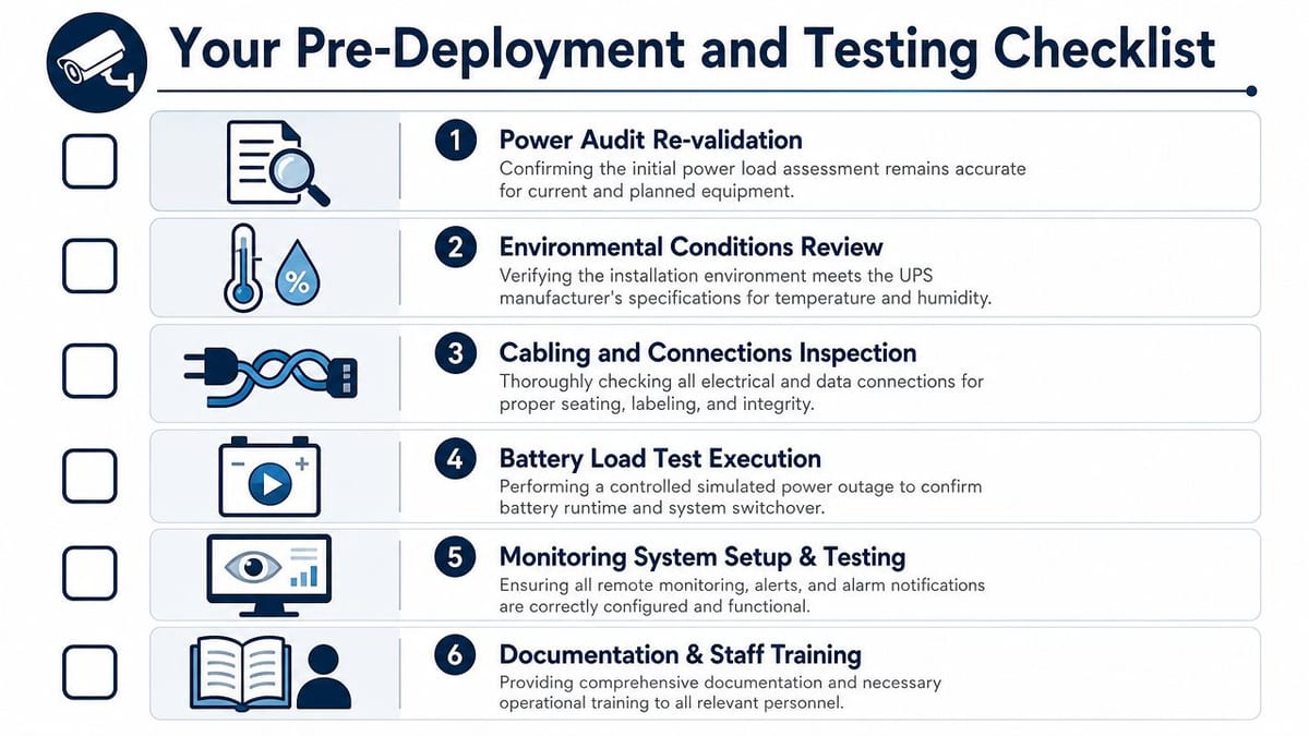
What to verify before go-live
Before handover, check the installed site against the design intent, not the last issue of the drawings. Late load creep is common. A few added switches, a recorder, upgraded locks, or a comms cabinet fan can cut runtime faster than expected.
Use a commissioning checklist encompassing the power path and the operating model:
- Re-check the protected load against the final installed estate and actual nameplate ratings.
- Confirm breaker settings, cabling, and terminations match the actual current path, including bypass arrangements.
- Validate ventilation and environmental conditions around the UPS and battery location, especially where batteries sit in small plant areas or comms rooms.
- Test monitoring and alerting so the remote team can see faults, battery condition, mains failure, and low-runtime alarms.
- Review maintenance access for battery replacement, safe isolation, bypass operation, and servicing of connected systems.
- Check certification and records for the commercial electrical installation and associated compliance documents.
The test that matters most
Run a controlled live outage test.
Remove the normal mains path under a planned method statement and watch the whole site behave as one system. Confirm UPS transfer performance, network stability, access control state, CCTV recording continuity, alarm delivery, and recovery when supply returns. Dashboard simulations and bench tests do not prove any of that in a real building.
If the facility is designed to operate without staff on site, this test carries even more weight. The real question is not whether the UPS stays on. It is whether the building stays visible, secure, and controllable long enough for the business to respond. The UK government's guidance on preparing for and responding to power cuts reflects the same operational reality. Outages happen, and sites need a tested response, not an assumed one.
If you have not tested the site under real power loss, you do not yet know whether the design works.
Maintenance is part of the sizing decision
A UPS that meets the calculation on paper can still be the wrong choice in service. Battery replacement intervals, site access restrictions, firmware management, spare parts cover, and the number of separate field devices with their own batteries all affect operating cost and failure risk.
Good projects plan for repeatability. Set a retest schedule. Record runtime results. Update the load list after changes. Make sure the operations team knows what the alarms mean and what action is expected. That is how UPS sizing becomes risk control, not just procurement.
A careful UPS sizing calculation is one of the best places to remove risk from a fit-out before that risk becomes downtime. If you're planning an office move, server room expansion, or an automated building environment, Constructive-IT can help turn the power, data, access and certification pieces into one buildable, testable infrastructure plan.